In this post I will be covering how I made a Wireless Controller for my Behringer XR18 Wireless Digital Mixer.
This past spring I bought a Behringer XR18 Wireless Audio Mixer for an event that I had coming up, as I decided it was time to invest in a mixer instead of borrowing one/renting one. The PC Control App for it is great, but when you are in the middle of a show, nothing beats physical knobs, faders and real LEDs for quick response times and visual feedback. And that is where this project comes in.
The X32/X-Air as well as the Midas variants have great OSC control, that can be taken advantage of super easily via all sorts of devices, weather they be a PC or a Microcontroller. The solution I came up with is not perfect and is clunky to use, but it was fun to build, and I wanted to see what I could do with what parts I had on hand. It also gave me a decent understanding of how the OSC protocol works, and a baseline to build future projects off of. This project should work with any device in the X-Air Family, and the Midas MR Family, but some channels/features may not work on the 12/16 channel models due to being designed for the XR18.
The Parts I used for this project comprised of:
WEMOS D1 Mini(currently $2-3 on Aliexpress)
MAX7219 Led Matrix Driver Chip
A Project Enclosure, in this case I salvaged a broken Aviom and re-used some of its knobs and buttons
For OSC(Open Sound Control) info I pulled heavily from Behringer’s OSC Info, as well as Patrick‐Gilles Maillot’s Huge page of OSC documentation.
Other Links for pages I pulled from for info, BCR2000 control of XR16 with Arduino and https://community.musictribe.com/t5/Recording/DIY-WiFi-MIDI-Remote-control-box-for-X-AIR-WORKING/m-p/257791, as well as some other pages I cannot find at the moment, but can be found using a search engine. The code for this project is mostly written by me, but sections of it are pull from other people’s sketches. This project is not perfect, and the sketch has some bugs and quirks, but after using it for the past 6 months, has proven very stable in a variety of situations.
This ZIP File Contains a Wiring Diagram, the Arduino Sketch, as well as some other helpful files.
For inputs and button mapping, due to the lack of input pins on an ESP8266(and bootup pin state requirements), some compromises had to be made. The ESP32 would have an advantage due to having more input pins, or a matrix could have been setup to use more buttons than chosen, but I did not do it that way due to wanting to keep it simple, and lack of parts on hand.
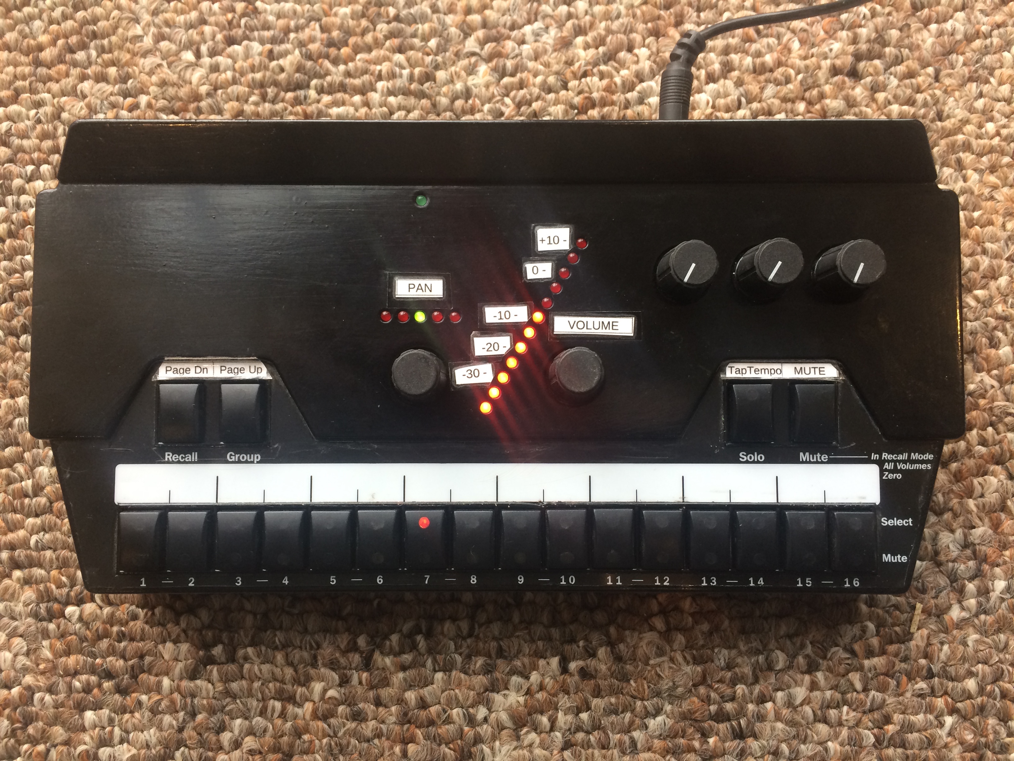
In the end what I came up with for controls was Page Up, Page Down, Tap Tempo and Mute Buttons as well as a Channel Select knob and a Volume knob.
The Tap Tempo button is set up to have the Stereo Delay Plugin in FX3, and is only changable in the sketch, but can be fully configured.
There are two “pages” of button controls. Page 0 controls parameters for Channels 1-16, and page 1 controls parameters for the Aux channel, FX1-4, DCAs 1-4, BUSes 1-6 and LR. If you are on Page 1, the Page Up LED will blink once periodically.
Most of the controls are self-explainatory, but there are a couple of “Features” built in as well.
If you hold down the Page Up button for 2 seconds, you can change the selected channel’s Pan using the Volume Knob, unless is it a DCA.
If you hold the Mute button for 3 seconds, any channel you select while holding the mute button will have it’s Mute status inverted.
If you hold down the Page Up, Page Down and Tap Tempo buttons for 10 seconds, it enters Config Mode and every LED comes on. It causes the ESP8266 to create an Open WiFi Hotspot that you can open in a web browser. The IP address for that page should be 192.168.1.1 unless the ESP8266 has already been connected to another network that used a different IP range, of which it remembers that range and re-uses it, and will always be *.*.*.1.
The web page will allow you to configure the WiFi network to connect to, as well as the IP Address of your X-Air/MR Mixer. If the controller fails to connect to the WiFi Network, it will just recreate the hotspot after a few seconds and let you re-enter your details.
If it connects to the WiFi network, but fails to connect to the mixer, no controls will work. This also applies if the Mixer is shut off, or not accessible from the network for any reason. To fix this, either put the mixer back on the network, or re-enter the WiFi config mode and enter the proper IP for the mixer.
I do not have any sort of error correction/ping set up, so if the mixer goes down at any time, the controller has no way of displaying the issue, it just stops responding untill the mixer is re-connected. All of the indicator lights pull their values from the Mixer, and the Mixer notifies the controller of any changes made. If the network goes down, or is flaky, the indicators will only update if the values on the Mixer have been updated, and will not change if you try to change a value with the network being down.
On bootup while connecting to a WiFi network, the controller runs a while loop that creates a pattern on the LEDs, as well as reading the buttons so you can enter Config Mode if need be. Once the ESP8266 has connected to the network all of the status LEDs go off, and it pulls the required values for Page 0 from the mixer, If the mixer is down this will fail and default values will be used for displaying on the status LEDs. When you switch to Page 1 it pulls the values for that specific page.
For the Aviom enclosure, I masked off the black plastic around the buttons using painters tape, sanded the surface slightly to help the paint adhere and remove the letters, then painted it with a couple coats of Glossy Black paint. The paint took a week to dry fully, but now the enclosure looks much better. The labels shown in the below video are just printed off onto plain paper, cut out and taped onto the case
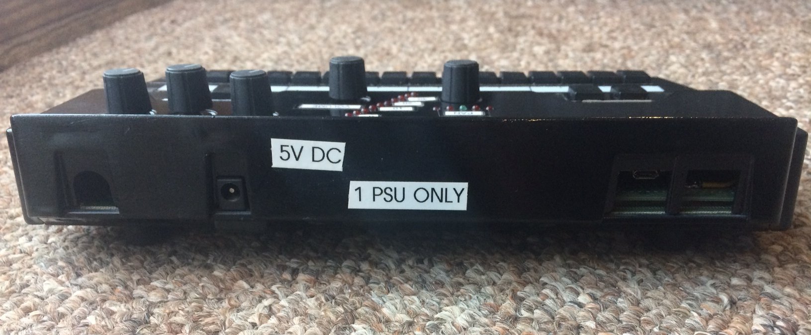
The WEMOS D1 mini’s Micro-USB port is directly accessible from the back of the enclosure, so updating the sketch is just a matter of plugging it in to a Micro-USB cable. The “1 PSU Only” notice is to remind myself that if I power it via the 5V DC Jack, it will put power back out the Micro-USB Port, and vice-versa. Don’t want to cook something major like my computer.
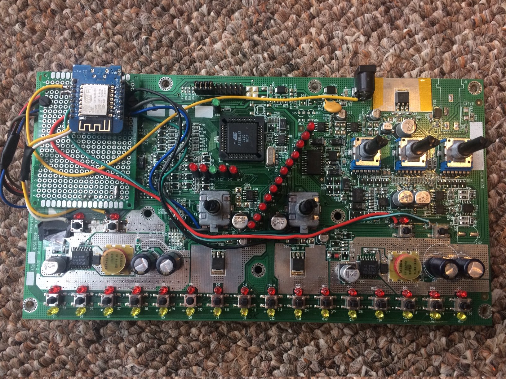
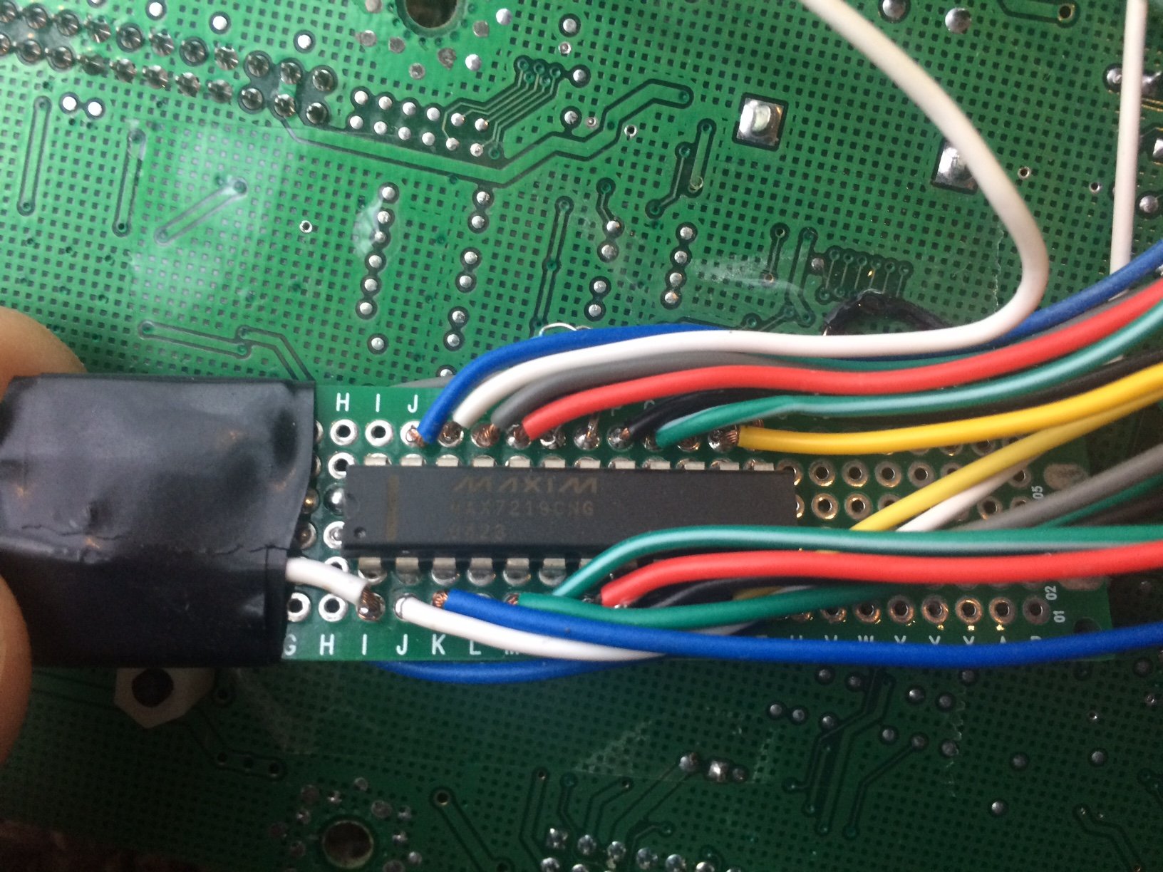
I used the Ground Plane on the Aviom Board to my advantage, so I did not have to run ground wires to all of the switches/rotary encoders. First I wired the WeMos D1’s ground to the ground plane. Some of the traces had to be cut for the switches because the old circuitry was causing both sides of the switches to be pulled low constantly, vs just when depressed. As for the LEDs, the Aviom board already has them set up in a 8 by 8 matrix, so it was just a matter of tacking the right wires onto the right pads, which was rather simple. There is alot of documentation on the MAX7219 online for wiring, and I have the diagram shown in the Zip File linked above as well. I put my MAX7219 on a daughter board with 5 wires going to the ESP8266 for power and data, and it tucks nicely in the bottom of the case. It is a very textbook use case for the MAX7219.
Yeah... lets put the cover back on it.
The daughter board with the MAX7219. Pretty, right? Wrong. But hey, it gets covered up anyways...
Close up of the Daughter board. Yes, I put insulating tape around it so nothing shorts out.
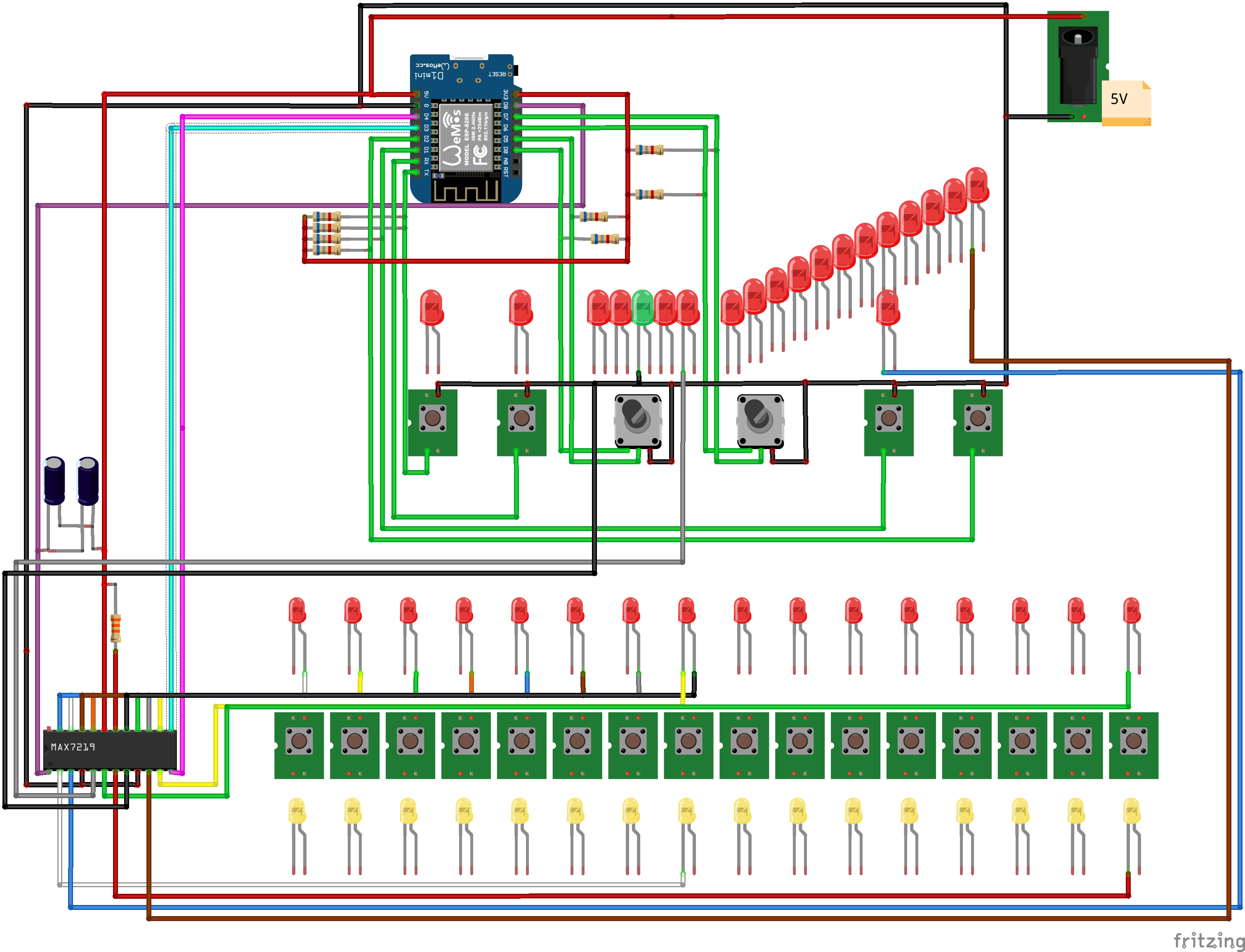
Hmm, hopefully I did not miss anything in this diagram.
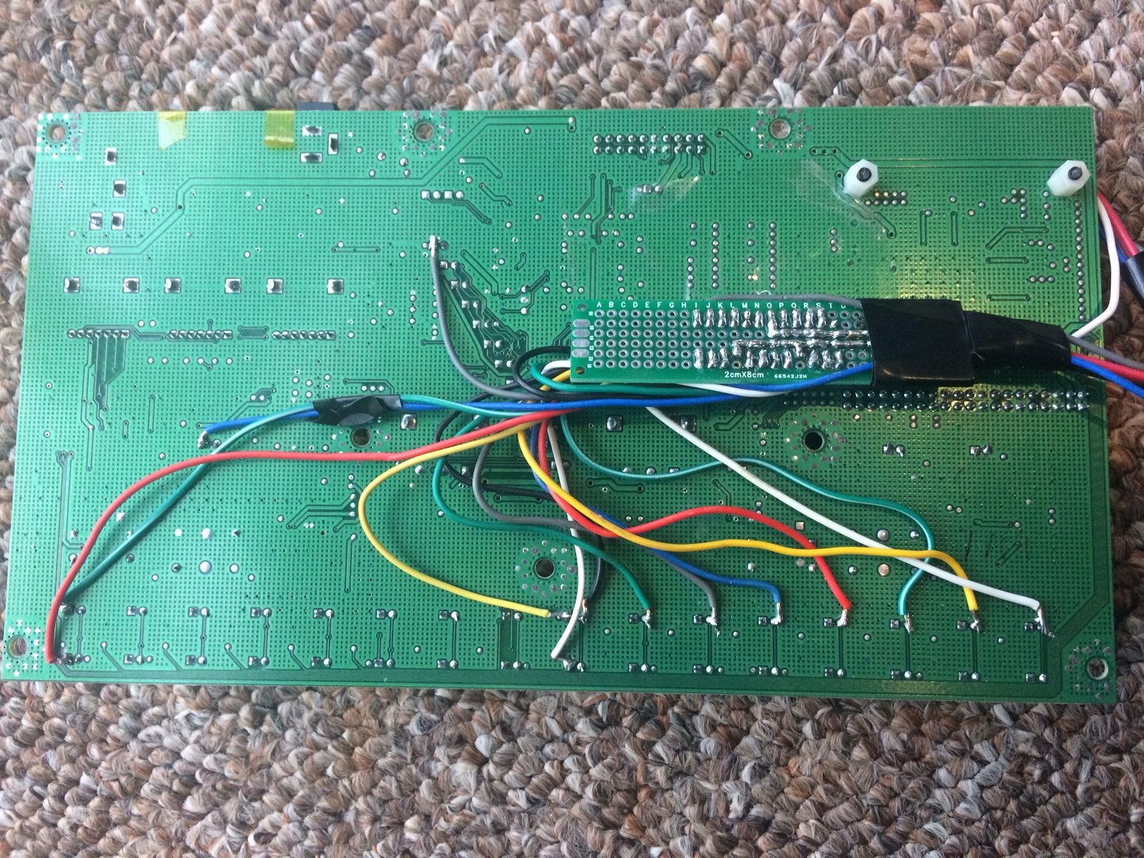
I snipped off the original A-Net Riser board from the Aviom, and managed to hook my proto-board onto some of the pins, specifically the ground plane pins.
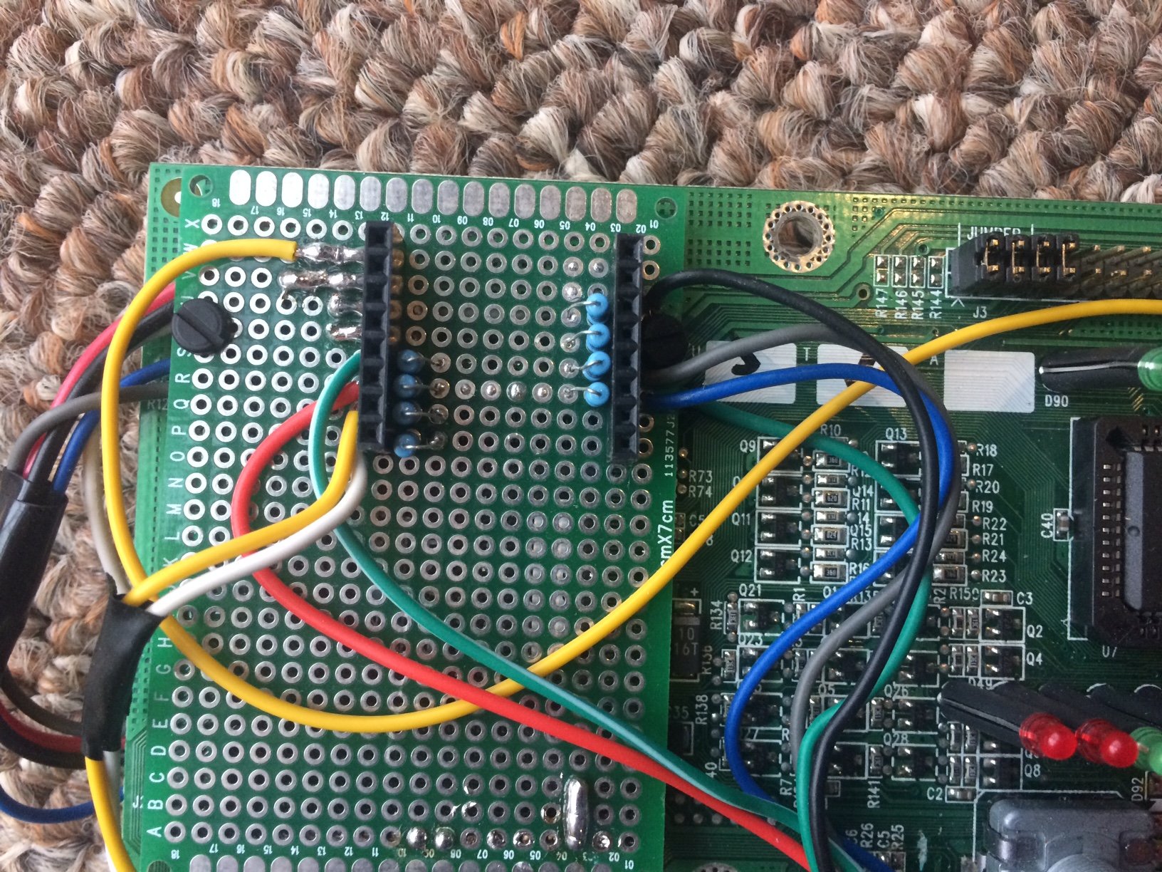
Look, another custom daughter board!
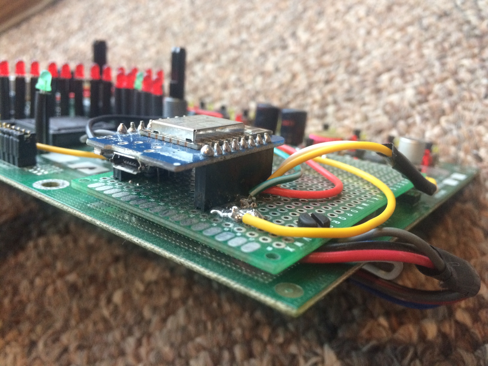
I had to remove the extra spacer and trim the legs on my WEMOS D1 mini to get it to sit low enough that I can plug a Micro-USB cable into the port with the case assembled.
As for things I would like to improve; The main issue I have is that the rotary controls are a bit finicky, and if turned too fast will go in a random direction, but it is not terrible. I have not found a solid workaround for this yet.
I think it would be neat to mod this to run on battery power by putting a USB powerbank circuit inside the case, and an on/off switch on the back. Im currently using it with a USB to 5.5MM cable and a USB power bank, which works very well also.
And here is a video if it in action! In this video the control is quite fluid, but if there is alot of WiFi traffic going on, or I am far away from the AP, usage may be “choppy”. I have never had an issue with it, but I do have a seperate AP set up in my rack that is dedicated to the XR18, and a couple of WiFI-phone controlled Aux Mixes.